Earth Mat Design Ppt
Earth Mat Design For Metro Station
Tiga Earth Mat Presentation
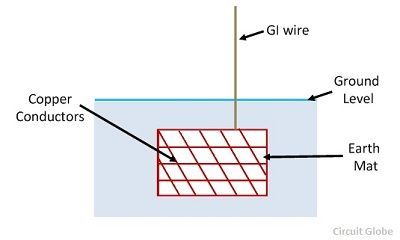
Procedure Methods Of Earthing Circuit Globe
Ppt Power Grid Design
Https Www Ijareeie Com Upload 2018 April 14 Eee2 Pdf

Earthing By By T R Sathyanarayana Rao T R Sathyanarayana Rao Ppt Download

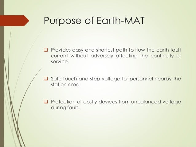
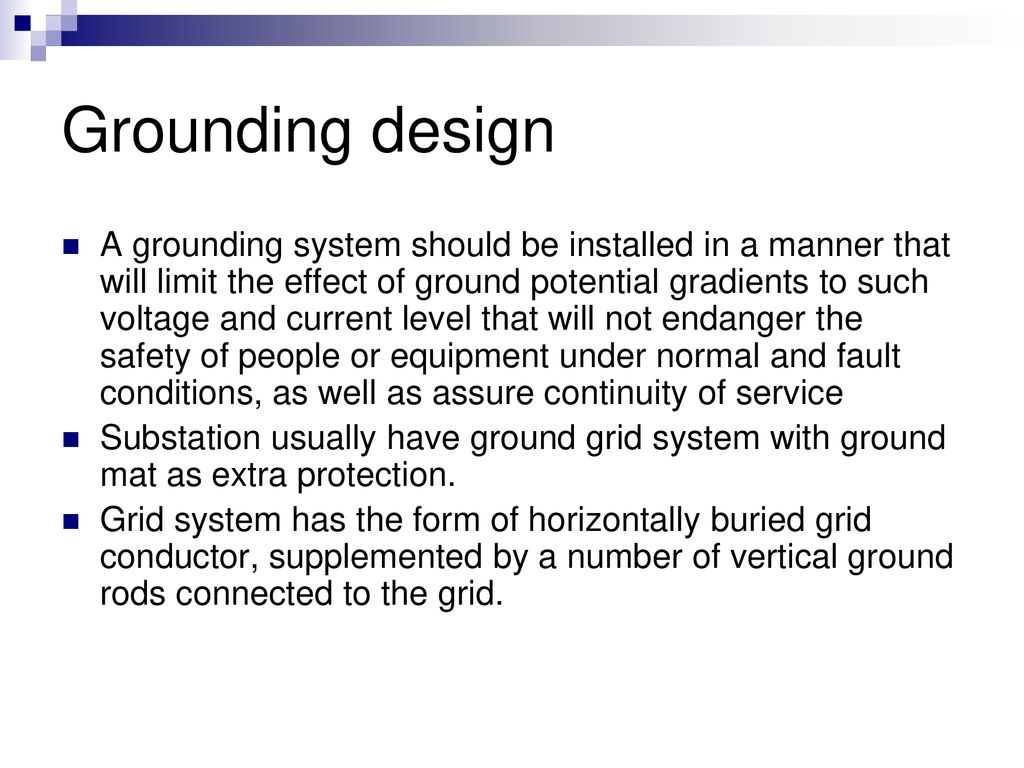
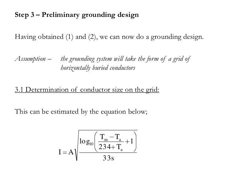
It is well that the earthing systems are intended to protect equipment and personnel in and around the substation from the dangerous over voltage.
Earth mat design ppt.
Chapter 5 Earthing And Bonding Ppt Download
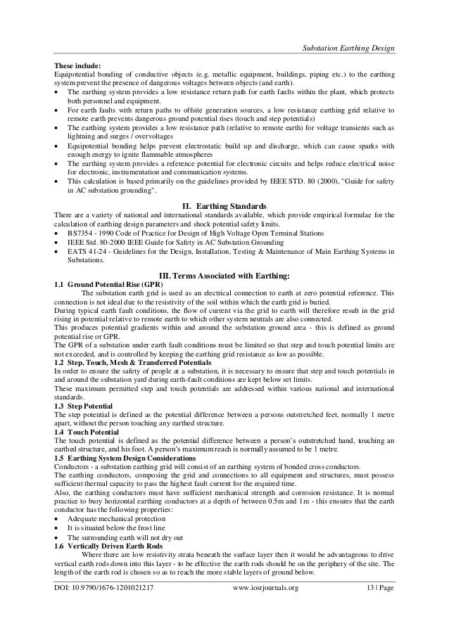
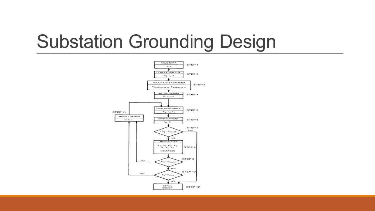
Substation Earthing Design
Presentation On Substation Design Ppt Video Online Download

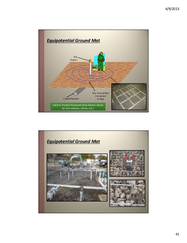
Tutorial Ground Mat Electric Shock Electromagnetism

Check Out Our Professionally Designed And World Class Earth Layers Ppt Template Download Our Earth Layers M Earth Layers Powerpoint Templates Powerpoint

Powerpoint Template Displaying Transparent Glossy Earth Globe On A Black And Gold Background Earth Globe Powerpoint Templates Templates

Free Animated Powerpoint Templates Powerpoint Animation Templates Free Free Ppt Templates Do Powerpoint Template Free Powerpoint Animation Powerpoint Templates

Download Premium Vector Of Pastel Memphis Pinterest Post Vector 2211709 In 2020 Powerpoint Background Design Poster Background Design Instagram Frame Template
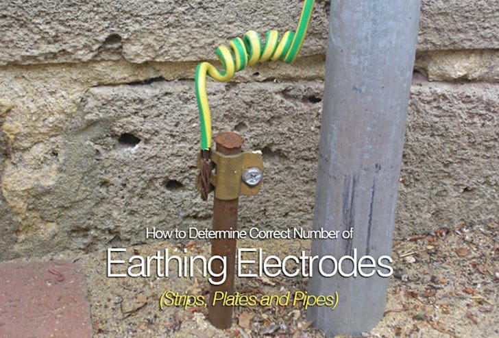
How To Determine Correct Number Of Earthing Electrodes Strips Plates And Pipes Part 1
Ecng 3015 System Earthing
Design Of Earthing System For Extra High Voltage Ac Power Substations Eep

Powerpoint Template Displaying Blue Earth Globe On Grid Patterned Background Background Patterns Blue Earth Earth Globe
Https Www Ijert Org Research Design Of Earth Grid For A 3311kv Gis Substation At A High Soil Resistivity Site Using Cymgrd Software Ijertv3is101000 Pdf
Presentation Induced Ac Interference Corrosion Mitigation

Rope Powerpoint Template Free Powerpoint Templates Powerpoint Templates Powerpoint Template Free Powerpoint

Medieval Manor Create You Own Draw Or Powerpoint 7th Grade Social Studies Powerpoint Student Created

Free Eco Earth Ppt Template Free Powerpoint Presentations Free Powerpoint Templates Download Ppt Template

Retro Black Powerpoint Templates Abstract Arts Black Brown Free Ppt B In 2020 Powerpoint Background Design Powerpoint Background Templates Background Powerpoint
Https Encrypted Tbn0 Gstatic Com Images Q Tbn 3aand9gcr Rut7qaokxq1lribz8bxdwood9xnvz Cobncb4kgmjaicyzgn Usqp Cau

100 Free Template Available For Google Slides And Powerpoint You Can Use In Your Presentations In 2020 Powerpoint Wild Adventures Google Slides

Goraden Google Slides Template By Aqrstudio On In 2020 Presentation Slides Templates Powerpoint Presentation Templates Powerpoint Presentation Design
Powerpoint Phase Powerpoint Design Powerpoint Keynote Template
Let S Talk About Strategy Extended Workshop What It Is Why It Mat

Guideline For Earthing Of Buildings And Industrial Plants
Source : pinterest.com
